Mechanical Seals Will Save You Money
Increasingly, mechanical seals are being used on fluid pumps for replacing lip seals and packed glands. Pumps that have these types of seals are more efficient and reliable performance over extended time periods. Mechanical seals are used to prevent the leaking of pumped fluids on the drive shafts.
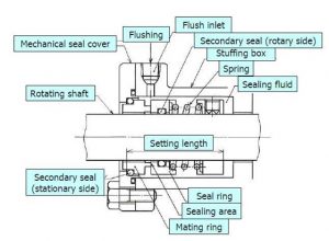
Between the two flat surfaces for the housing and rotating shaft is the path that controls the leakage. The gap for the leakage path varies, as the faces on the seals are subjected to external loads that vary. This tends to move the faces of the seals relative to one another.
Different shaft housing designs are needed for mechanical seals compared to other kinds due to the arrangement being more complicated and no support is provided to the shaft by the mechanical seals.
The faces of the mechanical seals are usually hydro-dynamically lubricated so that the mechanical seals will perform over extended periods of time with low friction. The fluid film has to be able to carry substantial loads.
 If a load does become too high, surface contact takes place on the film and bearing failure occurs. Generally, the lubricating film is a maximum of 3 micrometers thick. The thickness is crucial in order for the sealing function to work correctly.
Frequently, mechanical seals have one face with the right solid lubricant so that the mechanical seals are still able to operate without having fluid film for awhile.
The Use Of Pressure Balanced Mechanical Seals
The contact pressure of the mechanical seals can be reduced by using a mechanical seal design that is pressure balanced. A portion of the force that the pump fluid pressure generates is off set.
Mechanical Seals Design Features
Usually, three static seals are included in mechanical seals.
- Housing seal — usually a gasket o-ring.
- Seal between the sleeve or shaft and moving seal member- frequently an o-ring. However, it can be a vee or wedge seal. This kind of seal can’t be used with a bellows kind of mechanical seal.
- Sleeve seal- usually this is an o-ring.
These mechanical seals must need to be compatible with the associated environment and the fluid being contained. These seals might limit high temperature application designs. The best option in thee cases might be a metal bellows kind of mechanical seal:
Generally, the sealing faces are pressed together through the use of some kind of spring loading. There are several different kinds of spring loading systems that can be used.
- Magnetic
- Metal bellows seal
- Disc Springs seal
- Multiple springs that are distributed round the body of a mechanical seal
- Single spring mechanical seal
A single spring arrangement used with conventional mechanical seals. When space is restricted, another kind of spring arrangement is used.
 Usually the seal faces are made out of dissimilar materials. The softer face usually has the narrower surface.
Similar hard materials such as tungsten carbide get used for abrasive applications. Mechanical seal surface need to have enough strength for withstanding hydrostatic fluid force. Heat that is generated from the sliding action must also be removed.
 Frequently carbon is used against stainless steel, cast iron, bronze, silicon carbide and tungsten carbide.
The surface of the mechanical seals needs to be squared to the shaft, smooth and flat. Normally, both surfaces are lapped into a finish of high quality. The most important surface is the harder one. The design of the softer surface allows it to run-in past the initial operating time.
Shaft design is crucial. It needs to be rigid enough so that it can support the mechanical seals in their correct positions. The finish of the shaft surface needs to ensure that the static seals have good sealing (a minimum of 04. micrometers CLA).
The shaft’s Total Indicted Run-out needs to not be more than 0.125mm. Also, shaft vibration needs to be kept to a minimum. The shaft might get subjected to fretting corrosion. This results from seal micro-movements. Using sleeves or having locally hardened surfaces is frequently desired.
Cartridge Mechanical Seals
When it comes to the different components of a mechanics area of expertise, there is a wide array of tools, equipment and properties that range from the size of a giant centrifugal pump to as small as the nuts and bolts on a frame. But we will discuss one piece in general to understand better it’s function and uses.
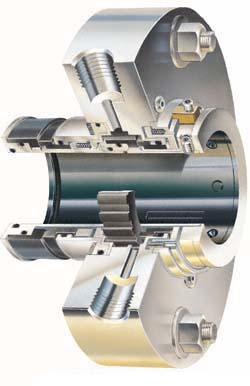
Cartridge Seal Cutaway
That is the cartridge mechanical seal. Just what is this item, and what benefits does it give? Let’s take a closer look at the answer to these questions, and as we do be sure to have a pen and paper handy to get down those important details.
To begin, the cartridge mechanical seal, as it’s name implies seals an object or piece of equipment tight not allowing debris to come in or liquids to go out. It is mainly used for rotating and centrifugal equipment and machines such as: compressors, blowers, mixers, and pumps. Obviously when a pump rotates the liquid inside can seep out between the shaft that rotates, and the stationary casing.
Because the shaft is in constant motion and rotates, it can be quite a problem to prevent such leakage. In the old days, early pump models used what is known as mechanical packing, but since the forties, seals have been quite popular and beneficial so have just about completely replaced packing.
An cartridge mechanical seal uses both sturdy and yet flexible materials to keep a tight close on a pump shaft as well as allow the ability to move freely and even spin within. You may have heard of similar seals known as O-rings, or radial shaft seals.
Mechanical Seal Fundamentals
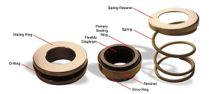
A mechanical seal should utilize four necessary aspects in its use: main sealing surface, secondary sealing surfaces, an actuating means of movement, and a driving means of station. Let’s consider these points one by one to understand fully the concept.
The primary sealing surfaces are the core of the process. The surface is almost always a hard material, such as silicon carbide, or tungsten, embedded in the pump casing, and a softer material, such as carbon in the assembly of the rotating seal. These two rings are in constant contact, one ring rotates with the shaft, while the other ring is motionless. These two rings are made using a specific process known as lapping. This process allows it to reach the appropriate texture and shape (flat being the norm).
The secondary sealing surfaces are the other aspects in the seal that require a fluid barrier but are not rotating relative to one another. Usually the secondary sealing elements are rubber diaphragms, O-rings, or PTFE wedges.
In an attempt to maintain the two primary sealing surfaces in close contact, a force of actuation is required to push on the seals. Usually a spring is utilized, or something to the like of a spring. In conjunction with the spring, the pressure alone of the sealed liquid can provide necessary pressure to keep the seals in close proximity.
What is known as a method of drive is a simple principle keeping the parts inside the equipment stationary. It goes without saying that the shaft must be the only part rotating in relation to the sealed ends. If the parts inside were to rotate as well, it simply would not be beneficial. This is where a method of drive comes in handy.
So we have the components, and the use, but how is the technology of mechanic end seals created? Mechanical seal face shaping is one of the most vital design elements within a mechanical seal. Seal face properties such as: centroid location, balance diameter, surface finish, surface area, drive mechanism, and face topography can be easily changed to achieve specified results in a variety of liquids. Seal face shaping is simply the change from a flat seal surface to a surface with a three dimensional appeal. Using an excimer laser, the first patent for such face-topography was released in 2007.
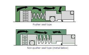
Aside from containing all of the elements mentioned earlier, all mechanical seals vary in the way their functional elements are arranged. Mechanical seals are usually put into two main categories: “Pusher” and “Non-Pusher”. These categories depend on whether or not the seal itself is stationary or dynamic. Pusher seals take the route of using a dynamic seal that moves along with the primary seal (usually an O-ring). Non-pusher seals will almost always use a motionless secondary.
As you look into the variety of seals used, it is easy to see that the number of different seals and different uses seems all but endless. From a complex seal to a cartridge seal, all end face seals help and allow a machine or centrifugal piece of equipment to run free of issues, debris, and leaks. We have gone over a few important details such as the components, the function, and the categories of mechanical end face seals. This information will benefit not only the reader but the one who applies these principles in the next choice of end face seals. As mentioned before there is a lot that goes into a machine, the ins and outs can be quite overwhelming. But when you know and understand even the small parts such as the mechanical end face seal, it can open your mind and make the job that much easier.
End Face – Mechanical Seal Number Fifty-Two
A gap seal is an important feature that is used with bearings or other parts susceptible to wear and tear. A good example is an O-ring.
A clearance seal is designed to fill or close the space between two parts, such as machine housing. The seal allows the parts to vibrate without causing damage. One example of this particular type of seal is called a floating seal. It is designed to be easily replaceable. These types of seals are normally made out of rubber or flexible synthetic materials.
Seal Piping
Since a rotating seal will build up heat from friction, the design must provide the heat a way to escape so it won’t cause the seal to overheat and fail. Generally a small tube is attached to allow the liquid to circulate and thus cool off. There are also filters and/or coolers that can be added to the tubing. These are usually based upon the pressure and temperature of the fluid. Each specific arrangement is assigned a number, defined by the API (American Petroleum Institute) in its specifications 610 and 682.
Component Seals
Component seals are generally considered disposable. Replacing worn items and/or refurbishing metal parts is usually not economically practical. These component seals are more economical than cartridge seals because they are produced in large volumes.
When purchasing seals it’s good to know that most are interchangeable. When it comes to size, the manufacturer doesn’t matter. The major differences between manufacturers are in the price and the quality. Component seals are generally expensive to assemble because they have to be assembled on the pump.
Tandem Seals & Double Seals
Almost every seal is designed to use gas or liquid to lubricate the seal face. As a result they are designed to leak. Hazardous vapors and dangerous chemicals such as flammable petroleum, cannot be allowed to leak into the ground or the atmosphere. That is why a second containment seal is used in addition to the primary seal on the pump shaft. The buffer space between these seals has a filling of a compatible or neutral gas or liquid, generally nitrogen. This acts as a buffer seal when not pressurized, or a barrier seal when it is under pressure.
Should a leak occur in a face-to-back tandem seal, the leak will go into the buffer fluid which is contained in the unpressurized cavity. This is normally referred to as the thermosiphon pot.
When an operator notes a dramatic increase in either the fluid level or pressure, he will understand there has been a failure of the primary seal. This information is achieved through transmitters or pressure/level switches.
If the cavity is drained of the liquid it’s an indication the secondary seal has failed. In either case, maintenance will be necessary to repair the problem. This is common whenever there are sealing fluids that change their state or could create a hazard if they come into contact with the open air. These things are detailed in the 34d edition of API 682, under Piping Plan #52.
In a back-to-back double seal, the liquid barrier found in the cavity between the two seals is placed under pressure. This means that, should the primary seal fail, the liquid barrier will not be pumped into the atmosphere but will leak back into the pump stream. Generally this application is employed when dealing with corrosive, highly toxic, abrasive, viscous and unstable fluids. More details are available in Plan Standards number 53A — also plans 53c and 54.
In addition, plan 74, although used exclusively for a support system with a dry gas barrier, can also be considered a double seal plan. In this case, however, the system employs a gas and not a liquid, usually nitrogen. Nitrogen has an inert nature which makes it better for mixing with the process stream which is being sealed.
Double seal and tandem terms are usually used to characterize seals based upon their orientation. For instance, double seals are mounted either face-to-face or back-to back. Tandem seals face-to-back.
This difference between unpressurized and pressured systems in both double and tandem seals has worked nicely to provide a descriptive notation of dual unpressurized and dual pressurized mechanical seals. The difference must be distinct since tandem seals traditionally utilize a pressurized fluid barrier as well.